
Rigol has launched new economic digital oscilloscope, Rigol 1054Z. Although considered as economic oscilloscope, but the specification is not that economic. Rigol equips this machine with 4 channels capability and...... Read More

During a lazy Saturday afternoon, there was a person asked on one of the mailing list about the orientation of the Bennic FPP capacitor. Unfortunately, I couldn’t find any Bennic...... Read More
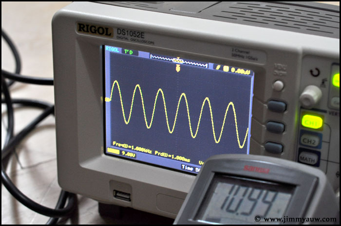
It’s a sunny Saturday. It has been agreed to have a measurement of some amplifier to check their power output. Located at Bintaro, I bring my Rigol Oscilloscope and Sanwa...... Read More

I’m thinking to create a first gift for my newborn (ooopsss… he is not yet here, just about to). A small MP3 Player with tiny amplifier to drive a small...... Read More

I was playing with my Rigol Oscilloscope to measure my laptop power output. The sound card was Realtek ALC660. I played a 1 kHz sine wave with a software and...... Read More

After reading my article about finding out capacitor inner-outer foil, some of my readers asked me to do the similar test on the resistor. Well, technically speaker, resistor shouldn’t have...... Read More

I just got my Oscilloscope, so I can play more fun with my DIY stuff. Ok, let’s start with some basic “game”, to find the inner and outer foil of...... Read More