
Asus Xonar Essence One uses a ribbon cable to connect the stage before the final buffer output to potentiometer then brings back the attenuated signal back to the buffer output stage.
This is no where a best approach, as the signal will pass through cheap ribbon cable back and forth. Some audiophile will prefer an extension rod and put the potentiometer on the back, near the signal point which to be adjusted, instead of bring out and back the signal itself with cable. Well, there are dozens way to Rome, right? 😉
The potentiometer itself (Alps B10K) is a balance type (4-Gang). I don’t really need that balance type as I will not use the balance output. So I did some tracing to get the connection between the LPF opamp to the final buffer stage. So here we go!
Remember that the layout below is seen from the top, not from the bottom. And I do hope I’ve done the tracing correctly 😉 Do at your own risk and double check before you proceed to modify that part.
“I” means Input, “O” means Output, and “G” means Ground.
One thing that you might notice is the Input and Output layout are all crossed. I1 is side by side with O2 instead of I2 and vice versa.
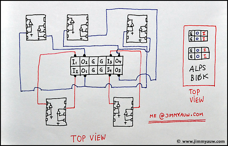
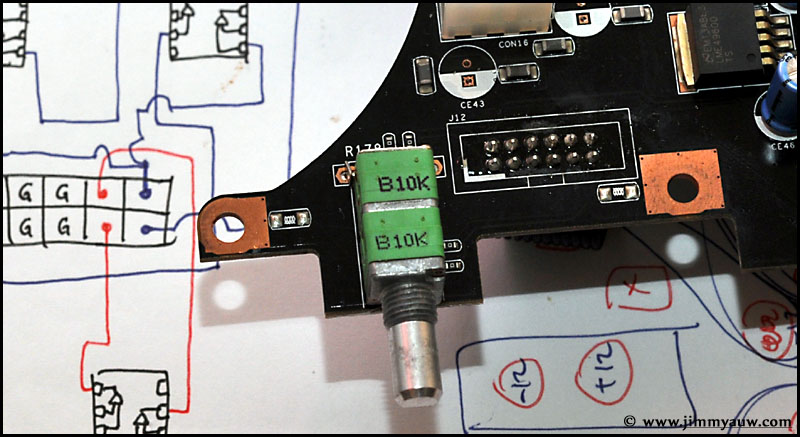
The real physical layout from the above schematic.

The Alps B10K 4-Gang potentiometer. Not the best, but it’s gonna be hard and a little bit expensive to change with another 4-gang potentiometer or stepped attenuator.


Agus
April 22, 2013 08:00Pagi Ko,
Dibypass aja ko 😀 ga usah pake potensio…
Nanti volume diatur d ampli atau pre amp 😀
suaranya potensio ini kurang bagus menurut saya.
Salam 🙂
Auw Jimmy
April 22, 2013 11:58Hi Bro Agus,
Saya belum berencana bypass, karena kalo bypass sih mendingan sekalian langsung dari LPF kita keluarkan (tidak perlu pakai final stage-nya lagi).
Suara ya relatif lah, masih banyak yang suka pake ini Alps Ijo koq 😉
Thanks.
audiodan
May 20, 2013 20:17Hi Jimmy
I’ve read with great interest what you’ve done on this DAC. I use it in a cMP2 based system (only the best PC audio system in the word, free and easy to assemble here the original link http://www.cicsmemoryplayer.com/
and the italian forum, very active
http://www.nexthardware.com/forum/cmp2-cmp-cplay/)
Now I’mn very interested to eliminate both potentiometers at all and the cables too.
I ask you if you think it will be possible to bridge the input of your scheme with the umbalanced output, excluding the signal from the long cable way and potentiometer too.
I’ve changed a lot of the line opamps on this DAC and finally I’ve found that 7 Burson dual are best, better than muses 01 too.
I think that’s better to remove the output electolytic capacitors too, the offset current is very low, no more than 4 mv
Auw Jimmy
May 21, 2013 10:42Hi Audiodan,
Surely if you read my schematic correctly (double check please), you can connect the input to output directly (so removing the need of potentiometer). This will bring very high gain, I believe. I would suggest to go with a stepped attenuator or you can go with dedicated high quality resistor to get the needed gain. No long cable needed (but you probably will disable the headphone output to).
Off course you can always remove the caps, especially if you have input caps on your pre/amp. But for safety reason, I will prefer to put it there.
Thanks.
audiodan
August 10, 2013 13:55Hi Jimmy
thx a lot for your response, very useful. I’ve got some troubles so my thanks goes so late!
Now I would make the job but…. some puzzlings are born:
– how must I couple the four points of ground with eight positive?
– If I need umbalanced output only, must I couple all input/output the same (I think it’s right but a confirm could be necessary)
If you are so kind to draw a simple scheme where coupling the 12 points of the pcb connector, so as to keep out potentiometer without touching cables under the PCB?
Regards
Daniele
Auw Jimmy
August 10, 2013 20:07Hi Dan,
I have no idea what you are asking, sorry.
I believe you better couple all in balanced, as some of them connected to the headphone amp section. That would be the safe bet.
The grounds are 4, but the other 8 actually 4 inputs and 4 outputs.
Thanks.
audiodan
August 18, 2013 14:32Hi Jimmy
I’ve made a cross bridge I-O (I1 joint to O1 etc.) on the pins near op-amp and now finally I’ve keep out that cheap potentiometer.
Obviously I’vnt nor volume control nor headphone amp section but I don’t need them.
Sound quality is clearly better and some silmic and cerafine are been added with success.
Output level is not so high (but my potentiometer was been always totally at max) and I’ve add 7 Burson dual opamp with a gorgeous sound quality, no one spider opamp could sounds like them!
Now I’m planning to build a separate PSU unit based on Belleson regulators, another real killer on PSU quality.
THX a lot for your help, I think that this ONE could become a very top DAC
Daniele
Auw Jimmy
August 19, 2013 21:06Hi Daniele,
Good luck then!
Thanks.
Sheldor
September 6, 2013 12:45The E ONE have no cap on the signal ?
Auw Jimmy
September 6, 2013 14:57Definitely, it has caps on signal.
Thanks.
Mario Silva
June 11, 2014 05:09I have Asus DAC essence one about one year, in the same day that a bought it, I changed the opamp to lm4562 and I am very happy with the result, but in the last week I read this post and I decided to disconnect the volume and headphone connector, I disconnected the cable and did the direct link between in and out, as you describe.
I am very inpressed with the result, IMO this is much better DAC without this part of the circuit, I strong recomend the others owners do this modification to, thanks for the tip.
Auw Jimmy
June 12, 2014 10:01Hi Mario,
Thanks for sharing! Enjoy the music.
Mario Silva
June 18, 2014 20:51Hi Jimmy, I notice in some musics a noise like sand, almost imperceptible , and I think is it saturation caused for high output volume of the dac. Before I cut out the volume circuit, I had ever notice that, and I had reduce the dac volume to eliminate this noise. I plan to remove the opamp that connect to RCA out ( I don’t use the balanced out), and I will link I1 and I4 directly to pins 1 and 7 in the socket of this opamp, the idea is remove the this opamp to reduce the volumes in some DBs. What is your opinion?
Auw Jimmy
June 19, 2014 19:11Hi Mario,
I dont think you can remove the last opamp and connect the input to output directly. What you can do (I think) is you can bypass the last opamp by taking the output from the I/V opamp and feed it directly to external buffer stage (or direct to preamp but I think you will need a short wire as without the final opamp, the current could be low).
Thanks.
Mario Silva
July 3, 2014 22:43HI jimmy, I was convinced that problem was in the DAC, that it was a kind of saturation, but actually the problem was a opamp in the amplifier, I changed the opamp and noise was gone, then I returned DAC to direct in-out configuration, with a great sound. I also changed the fuses to a “home made bypass fuses”, and I notice a great improvement in the sound, now I am wait for a AMR Fuses to have a protection on the equipment.
Auw Jimmy
July 8, 2014 15:53Hi Mario,
Good to hear on the improvement!
Thanks.
Mario Silva
December 14, 2014 01:14Hi Jimmy, recently I changed the amplifier to a micromega IA60 that has a more analitical sound, and I had to change the RCA opamp in the dac to get more bass, I used AD8066, but it is not enough, then I changed the RCA electrolytic coupling capacitor from 220 UF (original) to 10 UF, and now I am very happy with the sound, I have much more lower bass and midle bass. Do you know why they use this value (220UF) to this capacitor? I think It is high pass filter.
Auw Jimmy
December 22, 2014 22:19Hi Mario,
It’s simply a common value. Feel free to alter to other value if you think you like the sound.
Thanks.
Alan
January 23, 2015 17:58Hi Jimmy,
I want to replace the B10K potentiometer found in this since mine is crackling and getting worn out. I can’t find the exact same one anywhere online. Can you recommend me any good alternative one that will fit exactly right?
Thanks,
Alan
Auw Jimmy
January 29, 2015 16:55Hi Alan,
The only replacement that fits the size is the same green Alps.
Except you want to wire it out with cable, then you will have more options.
Thanks.
David
October 11, 2016 06:34Hi Jimmy,
Do you know where I can find the original Alps B10K potentiometer for Xonar Essence One Muses Edition? Mine is damaged and I need to replace it but I can’t find it anywhere. I have even contacted Asus service but unfortunately they replied they don’t have any replacement parts for Xonar Essence One. They provide the whole new unit during warranty period. It’s sad that you’re left alone with quite expensive device with no support when the warranty period ends…. Thank you in advance for any help. Best Regards
Auw Jimmy
October 17, 2016 23:00Hi David, maybe on ebay?
Thanks.